

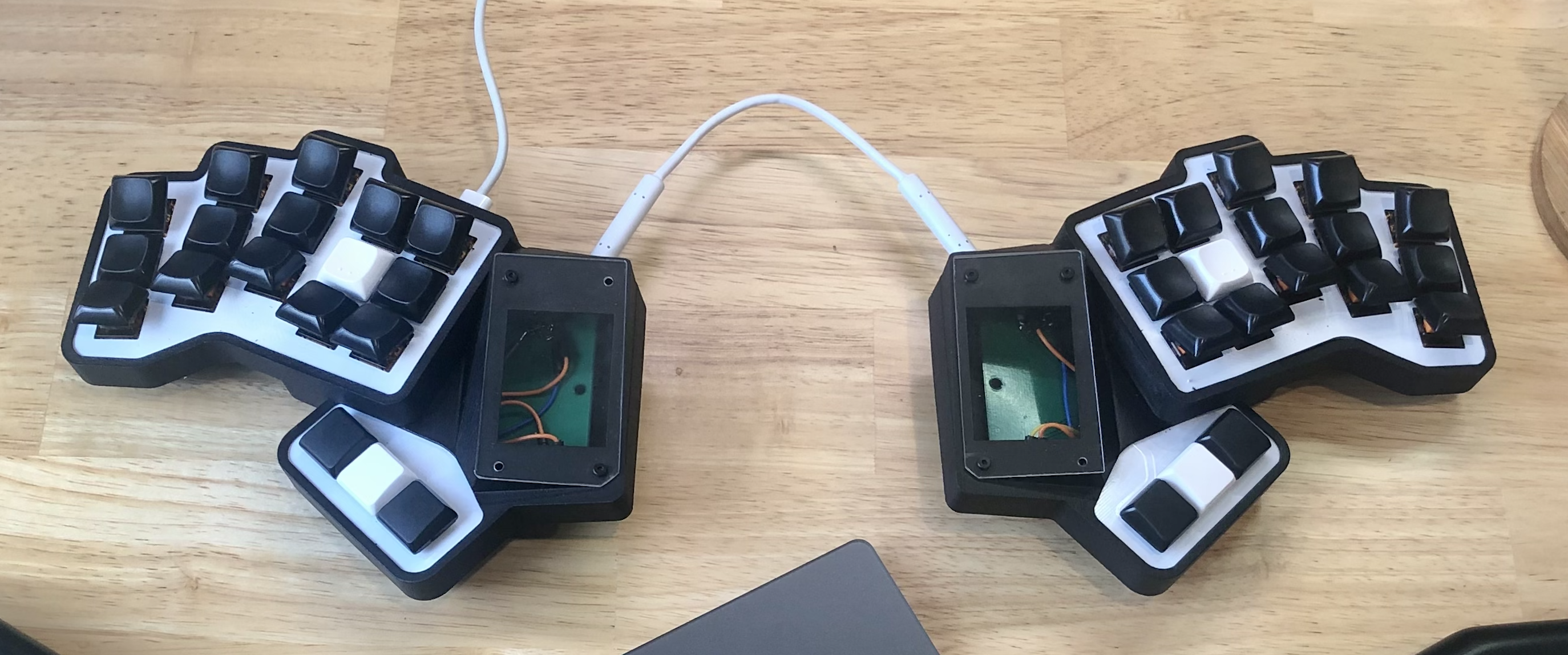
Tell me about your angled keys. This is the first I’ve seen them like this. What are they called?
They are custom angled risers I got printed. They fit between the switch and the keycap.
So they still push straight down? How does that feel?
It took a while to get used to them (like a day or two). But I’ve been using them on keyboards for a couple of years now, and it feels strange to not have them.
Do you otherwise have no spare pins? Also you can do communication between halves with only a single pin, what protocol are you using?
The other thought is, does the LCD use i2c and are you using i2c between halves too? If so, does the LCD modules have a way to change their i2c address so they don’t conflict? If so you should theoretically be able to have all of it share the same bus (the same 2 pins).
Oh that’s an interesting thought. All might not be lost after all! I’ll need to investigate.
At least it’s usable. My last pcb I screwed up the gaetreon holes completely. Why do they make key switches so obnoxious.
True. I’ve not yet added any code to manage the per key RGB. Hopefully they all work as planned too.
